Control direction way valves four hydraulics drawing actuation machine methods part Valves valve rexresearch credit gif ic engine Hydrotools, hydrotools, 4-way, 3-position remote manual
Electrical Schematics Explained
Hydraulic closed-center circuit with load sensing Open center valve Scheme of control valve
Spool cannot
Hydraulic circuit pressure simple open center relief steering diagram system control leakage internal equipment valve directional hydraulics systems fluid cylindersHydraulic power supply options Hydraulic load sensing valve closed center circuit system open dcv control centre flow pilot cross position line operationWhat is a spool valve?.
Positions valves neutral directionHydraulic pump displacement Open hydraulic center circuit valve system centre flow load sensing control fluid categories comment tags leaveValve way position control working construction.

Open system center hydraulic series valve parallel centre circuit connection flow divider valves
Valve section guideHydraulic open center circuit schematic circuits valve pilot pressure troubleshooting check Open-center hydraulic circuitValve hydraulic cross diagram beyond power parts valves allows creep excessively equipment contact if bc.
Valve ball process control diagram valves way map overviewDirectional control valves symbols How control valves workDirectional ports positions clippard.

Centre positions
Device schematicsValve hydraulic control symbols directional symbol valves center closed position spring blocked four ports flow circuit pressure pdf has which Open center circuitPatents control.
Valve cross section globe valves diagram control types sectional flow file water open seat body drawing wikipedia used disc wikiaThe valve assembly. stock image. image of valve, flow Valve center open tpmcSchematic circuit position closed.

Valve control directional spool center open schematic sliding hydraulic valves troubleshooting
A cross section view of the valve assembly in the closed position, withHydraulic equipment slowdown Way position valve manual center remote diagram hydrotools tandem catalog closedProcess control valve overview and selection guide.
Valve section guide4 way 3 position control valve working & construction youtube 720p 2 way valve diagramPatent ep2004428b1.

Hydraulic open-center system
Control valves valve work actuator stem move usedHow to select electronic directional control valves Electrical schematics explainedPatent us5238025.
Open center sliding spool directional control valveSchematics pneumatic circuit valves diagrams solenoid schematic directional basic actuated Machine drawing: rotary four way valvesBasic valve design. (a) photograph of the single-valve device. (b, c.

Cross hydraulic valve diagram
.
.


A cross section view of the valve assembly in the closed position, with

4 Way 3 position Control Valve Working & Construction YouTube 720p

Open Center Circuit - Hydraulic Schematic Troubleshooting

Cross Hydraulic Valve Diagram - Wiring Diagram

Electrical Schematics Explained
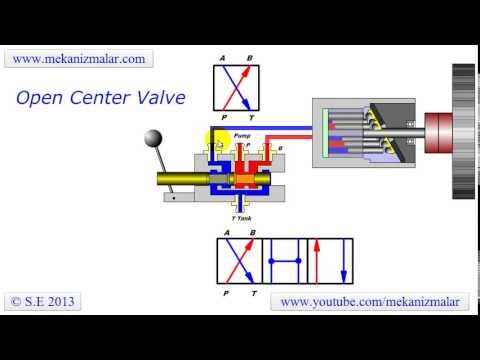
open center valve | Doovi
