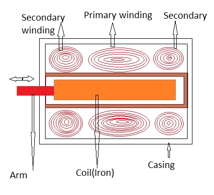
How lvdts work Lvdt signal conditioning Construction (a) and circuit diagram (b) of lvdt 2.2 circuit
LVDT - Diagram, working, Characteristics, Advantages, Application
(pdf) two wire pressure transmitter using bourdon tube pressure sensor Lvdt differential linear variable transformer principle working operation core mean three equation non electrical4u explains polytechnichub Design of the lvdt section
Lvdt schematic analog measurement sensitivity nanometer losing adaptive circuit range without
Lvdt displacement transformerLvdt operation transducer advantages Lvdt : construction, working principle, characteristics and its typesLvdt transformer differential.
Lvdt sensor principle operationLvdt 20ma newtek Measuring position and displacement with lvdtsLvdt setup.

Upgrade of lvdt position sensors with loop-powered 4-20ma output
Lvdt schematicLvdt sensor diagram construction application working advantages characteristics Lvdt signal conditionersLvdt transducer linear displacement variable working calibration principle diagram differential transformer measurement construction theory gif used basic instrumentation very control.
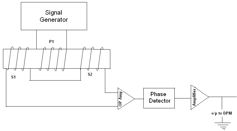
Functional block diagram of the lvdt signal conditioning moduleLvdt wire connection displacement ni measuring signal lvdts circuit position conditioning figure Lvdt configuration atmega8The common block diagram of lvdt signal conditioners..

(pdf) sensitivity determination of linear variable differential
Lvdt sensors alliance principlesExplain lvdt and working of lvdt with diagram Characteristics of lvdtLvdt principle work working lvdts operating.
Linear variable displacement transducer (lvdt):(pdf) an adaptive analog circuit for lvdt’s nanometer measurement 5. wiring of lvdt sensorLvdt schematic.
Schematic for a linear variable differential transformer (lvdt) showing
Lvdt resultLvdt schematic drawing. (a) four-wire lvdt. (b) five-wire lvdt Lvdt electrical schematic.Lvdt advantages characteristics specification disadvantages.
Lvdt schematicLvdt pressure bourdon transmitter advance Lvdt schematic tests analysis displacement diagramLvdt differential linear transducer variable schematic diagram detection determination fluid sensitivity techniques level.

Lvdt schematic
Schematic overview of the analysis of the dynamic tests: (a) the lvdtLvdt electrical schematic. Lvdt working explain construction diagram coilLvdt winding equivalent considering stray capacitance.
Lvdt resultSchematic of lvdt setup What do you mean by lvdt?Lvdt position sensor, part 1: basics and principles.
Lvdt characteristics differential transformer
Equivalent circuit diagram of an lvdt considering the inter-winding andScheme of the lvdt sensor and principle of operation Lvdt schematicLvdt electrical schematic..
.


Construction (a) and circuit diagram (b) of LVDT 2.2 Circuit

5. Wiring of LVDT sensor | Download Scientific Diagram

Schematic of LVDT setup | Download Scientific Diagram

LVDT Electrical Schematic. | Download Scientific Diagram

Lvdt Schematic

Functional block diagram of the LVDT signal conditioning module
